Current Sensing Theory
For a given current flow, a proportional magnetic field is produced around the current carrying conductor. NK Technologies current sensors measure this field using one of two technologies. For DC currents, we use “Hall Effect” while for AC currents, we use “Inductive” technology.
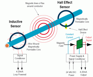
The Hall Effect sensor has a core, Hall Effect device and signal conditioning circuitry. The current conductor passes through a magnetically permeable core that concentrates the conductor’s magnetic field. The Hall Effect device is mounted in the core at a right angle to the concentrated magnetic field. A constant current in one plane excites the Hall device. When the energized Hall device is exposed to a magnetic field from the core, it produces a potential difference (voltage) that can be measured and amplified into process level signals such as 4-20mA or a contact closure.
The Inductive sensor has a wire-wound core and a signal conditioner. The current conductor passes through the core that magnifies the conductor’s magnetic field. AC current constantly changes potential from positive to negative and back again, generally at the rate of 50 or 60 Hz. The expanding and collapsing magnetic field induces current in the windings. This secondary current is converted to a voltage and conditioned to output process-level signals such as 4-20mA or contact closures.
[hr]Know Your Power
The current sensor is an economical and reliable tool that is indispensable for monitoring equipment status, detecting process variations, and ensuring personnel safety.
Controlling pumps, compressors, heaters, conveyors, and other electrically powered loads requires accurate, real-time status feedback. The conventional approach to this monitoring problem has been to use pressure switches, optical sensors, and zero-speed switches. Within the past 10 years, however, a growing number of design and process engineers have found current sensing to be a more reliable and economical way to monitor and control electrically powered loads. Solid-state current sensors are easier to install and more reliable than electromechanical devices–and they deliver more information.
Simply stated, measuring the current input to equipment gives you more knowledge about actual equipment performance. Seeing load changes instantly can help you improve throughput, reduce waste, and prevent catastrophic equipment failure. Continuous real-time monitoring of current draw can also be used for trend analysis or status alarming.
Methods of Current Sensing
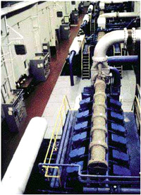
Current sensors facilitate the automation of industrial pumping stations by allowing real-time monitoring of pumps, compressors, heaters, fans, and other powered equipment. Measuring power input can help improve efficiency, safeguard personnel, and reduce motor maintenance costs in a wide range of factory applications. This photo was shot from an overhead crane at National Fuel Gas’s natural gas compressor station in Ellisburg, Pennsylvania. The five integral engine/compressors (large-bore, slow-speed, ~200 rpm, ~2200 hp), made by Dresser-Rand, are running in parallel. Each panel on the left controls and monitors an engine/compressor unit. (Courtesy of Basic Systems, Inc.)
The most common ways to sense current are resistive shunt, Hall effect, and induction.
Resistive Shunt
The resistive shunt is a calibrated resistor placed in a current path that produces a voltage drop proportional to the current flow according to:
V = IR
where:
V = voltage drop
I = current flow
R = shunt resistance
The voltage drop measurement is typically in the millivolt AC range. This output must be conditioned by a separate transducer into a process signal such as 4-20mA or a contact closure.
Unfortunately, the shunt presents serious operational problems and potential safety hazards. Both sides of the shunt resistor are at line voltage, which in practice means bringing 480 VAC into an otherwise low-voltage control panel. This lack of isolation can cause serious injury to unsuspecting service personnel.
Since it is essentially a resistor, the shunt is often perceived as the least expensive solution. Although it is in fact a low-cost device, the signal conditioner must be built to withstand 480 VAC and is very expensive. Installation and operating costs of the resistive shunt further restrict its use. Installing this device requires cutting and re-terminating the current carrying conductor–an expensive and time-consuming proposition. Furthermore, because the shunt is a fixed voltage drop (insertion impedance) in the monitored circuit, it generates heat and wastes energy. The shunt is suitable only for DC current measurement and low-frequency AC measurement (<100 Hz).
Hall Effect Sensor
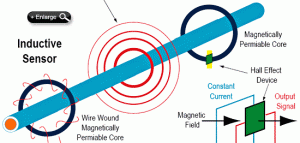
Figure 1. Hall effect and induction use different techniques to measure the magnetic field around a current-carrying conductor. The Hall effect sensor is best suited to DC current, and the inductive sensor to AC current.
Hall effect and induction are noncontact technologies based on the principle that for a given current flow, a proportional magnetic field is produced around the current-carrying conductor. Both technologies measure this magnetic field, but with different sensing methods (see Figure 1).
The Hall effect sensor consists of three basic components: the core, the Hall effect device, and signal conditioning circuitry. The current conductor passes through a magnetically permeable core that concentrates the conductor’s magnetic field. The Hall effect device is carefully mounted in a small slit in the core, at a right angle to the concentrated magnetic field. A constant current in one plane excites it. When the energized Hall device is exposed to a magnetic field from the core, it produces a potential difference (voltage) that can be measured and amplified into process level signals such as 4-20mA or a contact closure.
Because the Hall sensor is totally isolated from the monitored voltage, it is not a safety hazard and has almost no insertion impedance. It also provides accurate and repeatable measurement on both AC and DC power. Hall effect transducers require more energy than conventional loop-powered, two-wire systems. Subsequently, most Hall sensors are three-wire or four-wire devices.
Depending on the design, Hall effect transducers can measure frequencies from DC to several kilohertz. Because they tend to be more expensive than shunts or inductive transducers, their use is generally limited to measuring DC power. Compared to the inductive transducer, their major disadvantage is limited rangeability.
Inductive Sensors
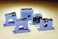
Photo 1. Inductive current switches are available in both solid-core and split-core configurations. These compact, self-powered devices provide field-adjustable set points and built-in mounting brackets to simplify installation.
The inductive sensor consists of a wire-wound core and a signal conditioner. The current conductor passes through a magnetically permeable core that magnifies the conductor’s magnetic field. AC current constantly changes potential from positive to negative and back again, generally at the rate of 50 Hz or 60 Hz. The expanding and collapsing magnetic field induces current in the windings. This is the principle that governs all transformers.
The current-carrying conductor is generally referred to as the primary and the core winding is called the secondary. The secondary current is converted to a voltage and conditioned to output process-level signals such as 4-20mA or contact closures. Inductive sensing provides both high accuracy and wide turndown, and the output signal is inherently isolated from the monitored voltage. This isolation ensures personnel safety and creates an almost imperceptible insertion loss (voltage drop) on the monitored circuit.
Inductive sensors are designed to measure AC power and typically operate between 20 Hz and 100 Hz, although some units will work in the kilohertz range. A well-designed inductive sensor can be configured as a two-wire device to reduce installation cost.
Applying Noncontact Current Sensors
Current sensors are frequently used to provide essential information to automated control systems, and as primary controllers in relay logic schemes. The two most common types are current transducers and current switches.
Current Transducers. Current transducers convert monitored current to a proportional AC or DC voltage or milliamp signal. These small devices have extremely low insertion impedance. Inductive transducers are easier to install because they are two-wire, self-powered (0–5 VDC or 0–10 VDC outputs), or loop-powered (4-20mA output) instruments. Hall effect transducers are generally four-wire devices and require a separate power supply. Because both types can be connected directly to data systems and display devices, they are ideal for monitoring motors, pumps, conveyors, machine tools, and any electrical load that requires an analog representation over a wide range of currents.
Variable frequency drives (VFDs) conserve energy and improve motion control through improved motor speed regulation. Silicon controlled rectifiers (SCRs) improve heater life by minimizing thermal cycling. And switching power supplies are small, efficient, and compact devices that are easily integrated with a wide variety of electrically powered equipment. All three technologies are based on high-speed switching, which distorts the AC sine wave. Understanding the two principal methods of amp measurement can help you specify the right device for these demanding applications.
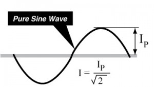
Most current transducers are of the average responding type, rectifying and filtering the sine wave to obtain the average peak amperage. To calculate the RMS current of a pure sine wave, the transducers simply divide the peak current by the square root of 2 (1.1414). This method provides fast response (100·200 ms) at a moderate cost, but it works only on pure sine waves (see Figure 2).
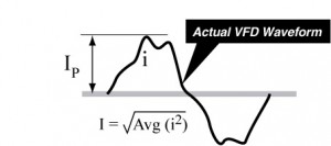
The output waveform of a typical VFD or SCR is not a pure sine wave. The simulated wave can exhibit peaks several times greater than the average current, and their relative sizes change with the carrier and output frequency. In these applications an average responding transducer can be accurate at 20 Hz, but 10% high at 30 Hz, and 10% low at 40 Hz. Average responding transducers simply cannot provide an accurate measure of these distorted waveforms.
Only true RMS measurement is capable of accurate measurement of nonsinusoidal waveforms found on VFDs, SCRs, electronic ballasts, switching power supply inputs, and other nonlinear loads. True RMS instruments measure the power or heating value of any current or voltage waveform. This allows very different waveforms to be compared to one another and to the equivalent DC (heating) value.
True RMS measurement begins by squaring the input waveform to mathematically rectify the signal. The next step is to average the wave over a period of time and calculate the square root. The output is the true power (heating value) of the wave (see Figure 3).
How can you tell if you have a true RMS transducer? If the product specification or data sheet describes the output as “true RMS on sinusoidal waveforms,” you have an average responding transducer and a clever spec writer. A true RMS transducer specification will be described in the datasheet as “true RMS on all waveforms” and “accurately measures VFDs or SCRs.” True RMS transducers typically provide a slower response than that of average responding transducers (400·800 ms) and may cost 30%·50% more than the average responding transducer.
Most current transducers are available in solid or split-core configurations to facilitate installation. The typical transducer uses field-adjustable span pots. More advanced devices feature jumper-selectable ranges to eliminate calibration labor. Typical transducer ranges are 0–2 A up to 0–2000 A, with apertures of 0.5 in. to >3 in. (12–76 mm).
Current Switches. Designed for monitoring and switching AC and DC circuits, current-operated switches integrate current sensing and signal conditioning with a limit alarm. The switch output is activated when the current level sensed by the limit alarm exceeds a user-selectable threshold. Inductive current switches generally feature solid-state output switches. They are self-powered and consequently are a good choice for retrofits, renovations, and temporary monitoring (see Photo 1). Hall effect current switches have either a solid-state or relay output. Their high power requirements preclude a self-powered design, and a separate power source requirement increases their installation cost.
Some current switches are shipped with a fixed set point. Newer designs provide field-adjustable set points with a potentiometer and LED or LCD feedback. Their set point ranges span from 0–5 A up to 0–2000 A. For relay logic systems, switches should be equipped with integral time delays to allow for start-up surge and momentary sags or swells.
Motor Monitoring and Control
One of the most common applications for induction current sensing is motor monitoring. Because current draw is such an excellent indicator of motor condition, the current sensor can be used to solve a wide range of process control, safety, and maintenance problems.
Automating the feed mechanism to crushers and grinders is often accomplished by installing a current transducer on the motor lead. The output signal is used for closed-loop control between the crusher and the feed mechanism. A drop in load signals the conveyor or loader to increase the feed rate, and a rise in load initiates a decrease in the feed rate. In this operation, controlling the feed rate helps prevent jamming, improves the uniformity or structure of the ground product, and enhances the efficiency of subsequent processing operations (see Figure 4, page 56).
The same control logic can be used to interlock two or more motors to ensure personnel safety. Here the objective is to start a second motor only after the first motor is running and driving its load. This type of safety interlock is used in a variety of commercial and industrial facilities.
Automatic load switching and status alarming are also typical applications for current switches. Often they are used to replace auxiliary contacts, which signal only the contactor position. Most motors are equipped with local disconnect switches at the actual load to facilitate maintenance. If equipment is taken out of service at the disconnect, the contactor’s auxiliary contact will give a false on indication that can have serious safety or operational consequences.
Smart self-calibrating current switches can be programmed to alarm overload and underload conditions or to start up standby equipment. These microprocessor-based devices feature built-in programmable timers that compensate for short-duration abnormalities and motor in-rush during startup. In these operations, the current switch is more reliable because it is not subject to contact corrosion or set point drift, and does not require periodic maintenance or calibration.
Current transducers and switches are also used to ensure motor protection and facilitate equipment maintenance procedures. Large electric motors need to be overhauled or rebuilt periodically. A predictive maintenance schedule, based on the actual number of motor starts, ensures proper operation and reduces the risk of motor failure. Installing a current switch on the motor lead, and using the signal to run a counter or feed into an automated system, provides an accurate count of motor starts. This information can be used to schedule preventive maintenance and reduce costly emergency repairs.
Current transducers are also installed on cutting tools to diagnose the tool’s effectiveness. If the tool is drawing too much current, its cutting edge is probably dull. Signaling the operator that maintenance procedures are required reduces the production of rejected material and prevents process interruption.
Pumps, Heaters, and Other Monitoring Applications
Current sensors are frequently used for protection against pump jams and suction loss. In wastewater applications, organic matter can jam pumps and cause damage to both the motor and the pump before thermal overloads are tripped. Alternatively, a blockage in the pump suction line can cause the pump to run dry, overheat, and damage seals. Installing a current transducer on one leg of the motor leads allows the operator to monitor both overload and underload conditions and take corrective action before the equipment is compromised.
The same technique is used to monitor equipment that supplies heat to manufactured products, storage systems, or recirculating material. If a heater fails, the batch or process may have to be scrapped. Integrating the current switch signal with the automation system allows the operator to monitor on/off status, alarm a failure, or automatically switch on a backup heater.
New Trends in Current Switch/Relay Technology
Two new trends are emerging in the current switch/relay market. Today’s smaller control panels and crowded switchgear are driving the demand for more compact units with higher ratings and more versatile mounting options.
Relays are typically used to start loads, and pressure switches or zero-speed switches are used to monitor them. This approach requires two installations and multiple conduit runs that increase the complexity of the system. Today, modular relays can quick-connect to a wide range of current sensors from adjustable set point current switches to single-piece transducers. This modular approach lets the operator switch on a motor, alarm the on/off status, and monitor the motor’s load condition with a single installed device.
The second trend is toward smarter relays. New microprocessor-based current sensors automatically self-calibrate on initial start-up. Other smart devices feature user-programmable timers that compensate for short-duration abnormalities and motor start-up in-rush. These enhanced control capabilities, higher ratings, and solid-state reliability have led to wider acceptance of current sensing technology as a replacement for conventional instrumentation.
Summary
Current sensors offer the design engineer and the process engineer a rich source of equipment “knowledge.” They are economical and reliable tools for monitoring equipment status, detecting process variations, and ensuring personnel safety.

