Finally in the 1960s, extensive research determined how much current and voltage were needed to cause ventricular fibrillation (where a heart stops beating) in humans. These studies showed that there are a number of conditions that increase the chance of death when there is contact with an energized circuit, and that fibrillation occurs with current as low as 70 milliamperes through the heart. Once the magnitude of current that the human body needed to be protected from was determined, methods of detecting this low level current and automatically disconnecting the offending circuit from the power source could be developed. The concurrent refinement of the transistor provided a solution, where current as low as 0.003 amps could be sensed, amplified and used to energize a relay.
In the years since the 1960’s, sensing ground fault leakage has undergone a rapid evolution. Advances in electronic and mechanical design have provided much more sophisticated and effective protection for personnel and the equipment they operate. The result is vastly improved safety in the home and in the workplace.
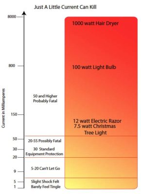
OSHA has published reactions in the human body to low level currents:
- 1 mA, a slight tingle is felt.
- 5 mA, a slight shock is felt, not painful but disturbing. The average individual can let go, but involuntary reactions can lead to injuries.
- 6–25 mA, painful shock, muscular control is lost.
- 9–30 mA, this is called the freezing current or “let-go” range. At this level many humans cannot get their muscles to work, and they can’t open their hand to let go of a live conductor.
- 50–150 mA, there will be extreme pain, respiratory arrest, and severe muscular contractions. The individual cannot let go, death is possible.
- 1000–4300 mA, there is ventricular fibrillation (the pumping action to the heart ceases). Muscular contraction and nerve damage occur. Death is most likely.
- 10,000+ mA, there will be cardiac arrest, severe burns and probable death.
Protecting Processes
The National Electric Code calls for ground fault protection on heating equipment in Section 427-22: “Ground-fault protection of equipment shall be provided for each branch circuit supplying electric heating equipment.” There is an exception: “In industrial establishments where conditions of maintenance and supervision ensure that only qualified persons will service the installed systems, and continued circuit operation is necessary for safe operation of equipment or processes, alarm indication of ground fault shall be required.”
In another section of the NEC, ground fault protection by definition means that circuits controlling heating loads must be disconnected when a ground fault is detected. But, no current magnitude of the fault is described. Because of this exception, many machines and processes do not need to be shut down until the process can be brought to completion. An alarm, whether audible, visual or electronic messaging, can be used to inform the operators that a fault has occurred and will need attention as soon as possible.
The industry standard for equipment protection is a current leakage of 30 mA. This is likely driven by the major suppliers of breakers and other protection devices so they do not have to offer adjustable trip points or countless model numbers. Plant managers have reported that they service overhead gantry cranes that leak over 200 mA on the best days, and much more when the weather is damp. The amount of current passing from the power feed to ground can be significant without this loss causing any problems other than wasting energy. What does tend to occur is that the fault current increases as time goes on, and may eventually be enough to damage the equipment by arcing.
The purpose of monitoring for fault currents depends on the situation, whether human contact could occur accidentally or the process could be damaged by the fault. Many users are checking for the failure of heating elements. Others may need to know when motor insulation is breaking down and allowing current to flow to earth. The point is to select a product that will do what is needed and react quickly enough to reduce damage.

Ground fault sensing has wide ranging applications such as melting ice and snow from sidewalks (photo courtesy Joel Silverman, Electrical Agencies in Colorado), or protecting industrial equipment and personnel.
Protecting People
One of the first things that people think of when they hear the term ground fault relay, is the power outlet in their homes and outdoors. While these devices perform a specific and desirable function, they are not designed to protect people from the hazards encountered in industry, where wet floors, long extension cords and higher voltages are common. Most of the residential designs are made to protect the occupants from shock from hair dryers in bathrooms, small power tools in garages and outlets around swimming pools and spas.
According to the 2017 National Electric Code, a 120 volt circuit that feeds bathrooms, kitchens, garages, unfinished basements, crawl spaces and outdoors must be protected with a circuit interrupter that will shut off power when leakage to ground exceeds 6 mA. The same protection is required in commercial establishments, protecting all bathroom and rooftop locations, construction sites, marinas, all wet locations in health care facilities, and around swimming pools and fountains.
While these outlets and circuit breakers provide protection against electrocution, the low trip point can be a nuisance in industrial settings. OSHA specifies that the trip point for ground fault circuit interrupters (GFCIs) in the named locations will be 6 mA.
This is effective where there are wet bare feet on a tile floor and a hair dryer in hand, but these conditions are seldom found in industry. The added insulation provided by boots and gloves helps protect personnel.
Where power tools are supplied using long, worn extensions cords, the leakage current can easily exceed 6 mA. The cords tend to pass small amounts of current between the conductors inside the cord due to cracked insulation or excessive moisture. Overall, a higher trip point may provide sufficient safety in industrial environments without spurious tripping caused by leakage through motor windings, deteriorating insulation quality, or capacitance leakage between conductors seen in very long runs of heat trace cables.
Methods of Ground Fault Detection
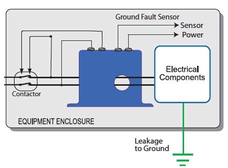
The primary method of ground fault detection is roughly the same now as it was fifty years ago. A single ring of magnetically-permeable metal wound with many turns of small gauge wire, a current transformer or toroid, surrounds all of the current-carrying conductors (Fig. 1). Whether single or three-phase power, if there is more current supplied to the load than is returned to the source, this sensing toroid produces a low voltage in the windings. This voltage is amplified and eventually used to trigger an action such as energizing a solenoid to open a set of contacts.
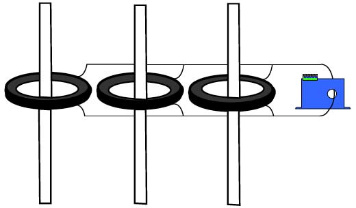
Another way to detect ground fault current is to place a toroid over each conductor and connect the secondaries together, with a sensing device installed to monitor the resulting circuit (Fig. 2). Each toroid or current transformer must be rated to handle the maximum current in each conductor. The accuracy of this multiple toroid method is inherently less precise than using a single toroid due to manufacturing and material tolerances. It is nearly impossible to make a current relay which can accurately detect and measure extremely low level current while also measuring the primary current magnitude. As an example, if the primary circuit draws 200 amps, the relay may report that 200 amps as a value between 198 and 202 amps (1% accuracy). Using a toroid designed to measure 0.003 to 0.10 amps could report a 30 mA fault as a level between 29 and 31 mA (1% accuracy).
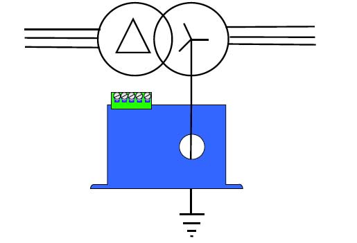
Still another detection method that can be used when the need is to monitor the entire load of a machine or distribution panel supplied by a wye (star) connected transformer and bonded to earth at this location (Fig. 3). Passing only the bonding conductor through a ground fault relay will perform the same function as using a large toroid over all the conductors in order to detect an imbalance in the vector sum of the feeding circuit phase angles, and thus equating to a ground fault.
In most industrial applications where ground fault sensing is required or desired, the relay output is used to perform one of two operations: (1) A contact closes a circuit to energize the operating solenoid of a shunt trip circuit breaker or, (2) A contact opens a circuit powering a contactor or motor starter operating coil. How the relay output interacts with the rest of the control system is completely at the discretion of the system designer.
Shunt Trip Circuit Breakers
Circuit breakers come in a huge variety of styles. Some are designed to accept accessories to increase product versatility, such as, under voltage trip, alarm contacts, and interchangeable trip plugs. This paper focuses on the shunt trip options, which allow the breaker to be opened from a remote location (acting in the same manner as if there was an over current condition). This action is most commonly accomplished by using a magnetically operated solenoid to push or pull a latching mechanism to open the breaker contacts. In some applications, the shunt trip device is used to turn off a load in an emergency. For example, most auto fuel dispensing stations have an emergency switch that will disconnect all the pumps if there is a problem. This switch closes the circuit to operate a shunt trip breaker. The circuit breaker has to be reset manually after the shunt has operated, allowing safe removal of power in an emergency.
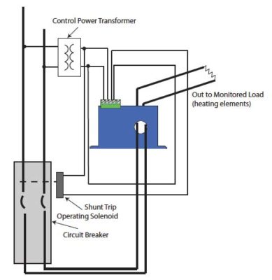
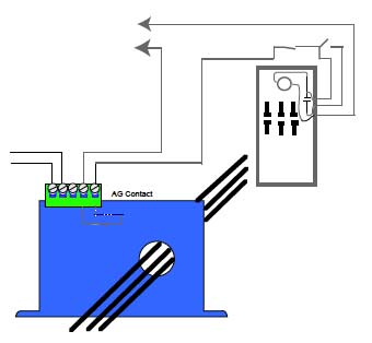
For shunt trip use with an auto-reset ground fault relay, when a fault over the relay trip point is detected, the relay contact closes the circuit to the shunt solenoid. As in other cases, after the cause of the fault is determined and mitigated, the breaker will need to be reset by hand. Since the power to the monitored load is completely turned off, and the only way to restore power is to reset the circuit breaker, using a shunt trip accessory effectively transforms an automatically resetting relay into a latching device. Even if the cause of the fault is removed from the load and the relay remains powered from an isolated source (which is highly recommended for all installations), the load cannot be energized until the breaker is reset (Fig. 4).
A latching output relay, like the auto-reset models, is typically equipped with a test button integral to the relay. Two additional terminals allow attachment of an external contact, usually a button mounted to the enclosure door, enabling the relay to be reset after a fault is detected without opening the panel. At least one manufacturer’s relays provide capacity to install several reset buttons, allowing the relay to be reset from multiple locations.
Magnetic Contactors
Another common method used with a ground fault relay is to have the contact open the circuit providing power to a contactor coil, resulting in de-energizing multiple heating elements or a motor-driven load such as a pump or fan. Opening a contact in a control system sounds easy, but in most ground fault sensing applications, the contact must be closed before the monitored load is energized.
Manufacturers offer both normally energized and normally de-energized versions of auto-reset ground fault relays. The more common of the two is normally de-energized, in which the output, whether solid-state or electromechanical relay, does not change state unless there is a fault to ground exceeding the trip point. The normally energized version is sometimes referred to as fail-safe. With this type of relay, the output changes state when the relay is first powered. The output returns to normal or shelf-state condition when one of two things occur: (1) The fault current sensed exceeds the trip point or, (2) The power to the relay is removed.
If a designer selected a normally open, normally energized solid-state output model to open the circuit powering a contactor coil, then the output contact would be open at shelf state and closed when the monitored circuit is not passing current to ground and the relay is energized. If the relay power is interrupted, or the monitored load passed current to ground over the trip point, the relay output will open, turning off the monitored load. This should be quite clear that the monitored circuit might not energize if the relay did not see power first, as energizing the relay closes the output contact. More commonly the relay selection would be normally closed, normally de-energized (solid-state) with the contact opening only when current over the trip point passes to ground.
With electromechanical relay outputs, the operation is the same. In normally energized versions, the output relay is energized with relay power applied so that the contacts change state when the relay has power. The relay will then return to shelf state when there is a loss of power to the relay or the fault current exceeds the trip point. (Fig. 5)
Another feature that should be addressed in the design of the control system is that auto reset means that if the fault current that trips the relay is removed or drops below the magnitude of the setpoint, the relay output will again return to the original or prior-to-fault condition. It is recommended that when the relay output is used to control a contactor, a three-wire wiring method is used, like a standard momentary motor start/stop button setup, so the contactor must be re-engaged after the relay trips. Alternatively, a latching output version of the relay is selected. In some code jurisdictions a contactor might not be considered a circuit disconnect. The local inspector, specifier or governing agency has the final say.
Probably the best place to monitor a circuit for ground faults is in close proximity to the load, rather than a distance upstream from the load. Many system designers tend to specify relays which will be monitoring several loads at one time by installing the relays before a final distribution point. While cost effective, any minor leakage issue in each load will accumulate or be additive, resulting in a higher leakage current level.
As an example, visualize a machine that produces silicon wafers used to make electronic components. There are several heating elements used to warm water and chemical wash processes, and there are several motors for product positioning as well as transformers adjusting voltage levels for various process controls. If the motor and transformer loads are monitored for faults individually, and the heating elements are also monitored with separate relays, the relays can be set to trip at relatively low levels. However, if a single relay is used to protect all loads, the trip point will likely need to be set much higher, hence reducing the protection level of each piece of equipment.
Heating elements seldom leak low level current as do motors and transformers. In most cases when they fail, there is a direct short to ground or the circuit is completely open. Heat trace cable runs do tend to leak small amounts of current to earth or there may be capacitance losses in long runs. With loads such as motors and transformers, the small imperfections in the varnish insulation of the windings can allow current to pass to earth at very low levels. While current magnitudes of 3 or 4 mA (one thousandth of one amp) can seldom be felt by a human and will not cause arcing or damage to equipment, this low level fault can increase over time until it does become a concern both to equipment operators and the equipment itself. At least one manufacturer has relays available which produce an industry standard 4 - 20 mA output directly proportional to the fault current. These relays monitor the zero sequence or fault current in similar fashion to contact output types, and are extremely accurate even with fault current below 5 mA.
Conclusion
Since the acceptance of ground fault relays in the middle part of the 20th century, countless lives have been saved by reducing the chance of electrocution. As regulators increase the number of places where they must be used and the technology improves, the number of deaths from shock will continue to decrease. By specifying where the fastest and lowest current sensing is needed and allowing for higher trip points where the chance for shock is reduced, the possibility that these important safety devices are bypassed is minimized. Nuisance ground fault relay tripping will keep workers from getting their tasks completed by turning off their power tools, and they will often find a way around the circuit protection. The best ground fault protection methods are ones which monitor individual circuits and disconnect the fault before shock or fire can occur.

