When the AC load exceeds 200 amps, it has always required a current transformer (CT) permanently connected to a 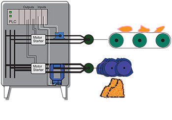 separate box enclosing a current relay. Setting the correct trip point is a challenge, since the same remote box is used with any CT ratio. The setting depends on the amount of current through the CT and how much of that current will cause the relay to change state. Most CTs produce 5 amps in proportion to the primary circuit current, so if the CT is wound for 800:5, 800 amps will create an output of 5 amps. If the load maximum current is 650, that is 18.25% of the CT maximum, so this primary circuit will produce 4.0625 amps, plus or minus 1%. The current relay would be marked to adjust the trip point as 0–5 amps or 0–100% of scale. Difficult enough to figure out with a calculator, and much tougher in the field. NK Technologies has reduced the complexity with the new ASXP-LS Large Current Switch.
Select the ASXP model with a range higher than the current you will need to monitor (select an 800 amp range for a load of 650 amps as above), and the trip point will be set with a potentiometer located on the side of the sensor base. The desired setpoint can be chosen by turning the potentiometer arrow to the amount of current which will cause the output relay to change. The label will show where to leave the potentiometer, marked clearly in 100 amp increments, but fully adjustable across the entire range.
The ASXP-LS current operated switch can provide protection against motor damage by tripping the output contact when there is an over load condition. If the application is such that an over load occurs regularly like in a grinding or material reduction process, the output action can be delayed for up to 15 seconds so the alarm occurs only when the over load is sustained for longer periods of time. Alternately, the contact can be actuated every time the over load occurs, and be used as a counter so that an operator knows how many times each shift the drive has been over loaded, with action taken through a controller if it occurs too many times in a set time period.
When used to monitor a large pump system, the trip point can be set to detect under current conditions, which occur if the head pressure is reduced due to a dry or blocked intake or an open discharge. The ASXP-LS is designed to monitor primarily high current loads, so an open discharge line would mean hundreds of gallons of liquid spilled in a matter of seconds.
If a drive belt is slipping or breaks, or a coupling shears the ASXP-LS will detect the problem quickly so action can be taken. There is no need for a pipe penetration like a pressure sensor, and no need to disconnect the power cable to install the sensor.
The New ASXP-LS Series - Engineered with Great Features
The engineering team has designed the ASXP-LS with features to make monitoring high current loads easier:
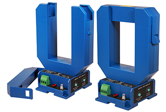
Split Core Housing: Allows the sensor to be installed after the conductors are in place. Pull the top bar off the sensing ring and set the sensor underneath the wires or bars.
Extra Large Sensing Aperture: The 2.3 inch wide and 3.42 inch high window easily accommo- dates the conductors. Multiple wires per phase can pass through without extra effort.
Electromechanical Relay Output: Will work on AC or DC control circuits, and can be used for no-volt inputs such as timing relay triggers.
LED Indication: A single LED shows Green when the sensor is powered and Red when the output has tripped.
Easy Installation: Designed to snap onto a DIN rail, or be attached to a back panel with screws through the sensor base.
Delay on Load Start: Designed to bypass inrush current. The delay is adjustable to allow large motors to start against high inertia loads without tripping, like a loaded conveyor.
Selectable “Fail Safe” Operation: Can be set in the field so it will act like a self-powered current switch: The normally open contact closes on current rise only. With the flip of a switch, the sensor output relay will change state as soon as the sensor is powered on, then if current rises over the trip point or power is removed from the sensor, the relay will change state. This provides the best level of protection for critical loads.
Wide Range: With four models available, the trip point can be set between 200 and 1600 amps. The adjustment is made with a potentiometer on the sensor base, with a range of 400 amps in 180 degrees of swing to the knob.