Designed & Assembled in the USA
A voltage transducer measures AC or DC voltage and converts the measured voltage into a proportional analog output signal.
Voltage transducers are sometimes called voltage sensors and less frequently voltage transmitters. Manufacturing and industrial applications use voltage transducers to monitor and control both processes and equipment.
What is a transducer?
transducer: “a device that receives a signal in the form of one type of energy and converts it to a signal in another form: A microphone is a transducer that converts acoustic energy into electrical impulses.”
Source: https://www.dictionary.com/browse/transducer
A transducer is a device that converts one form of energy into another. This process is called transduction. Examples include temperature, pressure and of course voltage transducers.
In electrical applications, a transducer will take a voltage or current range as an input and convert that input into a proportional analog output signal that can then be used as an input into control systems and measuring equipment.
What is a voltage transducer?
A voltage transducer converts a voltage input signal into an output signal. While the input range may vary widely, the output signal is typically an industry standard analog current or voltage range such as 4-20 mA or 0-5 VDC or 0-10 VDC. These industry standard outputs can then be used by displays, PLC’s and other data collection devices designed to use those analog output ranges.
How does a voltage transducer operate?
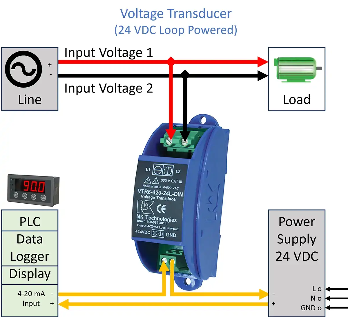
The voltage transducer’s operation is straight forward. It measures the voltage between two line inputs and provides an output signal that is proportional to the measured input voltage. The output is then fed to a digital display or data collection or process control device such as a Programmable Logic Controller (PLC). An external power supply is also required (typically 24 VDC/VAC or 120 VAC).

Advantages of using a voltage transducer or sensor
A voltage transducer can be used in a control system to provide 24/7 monitoring of processes and equipment. Monitoring the voltage powering equipment is important for several reasons. By monitoring voltage continuously, you can detect problem conditions early and prevent breakdowns and downtime. For example:
- Prevent over-voltage and under-voltage conditions that can have adverse effects on motors and equipment.
- Detect Power Failures: Notify Operator and either shut down production equipment in a controlled manner or enable an alternative backup power source.
- Detect phase loss when a three-phase circuit experiences a significant voltage drop and/or complete loss of one leg (phase).
- Signal an alarm condition to the operator of a pending fault condition and prevent equipment damage.
Voltage Transducer Input Voltage
A voltage transducer is designed to operate over a specific range of input voltages, either AC, DC, or perhaps both.
Unique products target low voltage, high voltage, and even bi-directional voltage ranges. Some voltage transducers are designed for either AC voltage only or DC voltage only. Others will support both AC and DC voltage over a defined input range.
Many input ranges will start from zero volts up to a maximum voltage. To get the best resolution, choose the closest available input range that is above the maximum expected voltage.
For DC input voltage, standard transducers measure from zero volts up to a maximum DC voltage. Bidirectional transducers measure a plus/minus range around zero (i.e. a transducer with an input range of +/- 300 VDC will measure voltage between -300 and +300 VDC).
Voltage Transducer Output Signal
Voltage transducers produce an output signal that is proportional to the input voltage. Three industry standard analog output signals are 0-5 VDC, 0-10 VDC, and 4-20 mA. The 4-20 mA output is common for industrial and factory monitoring equipment and is often preferred for new installations.
Three examples are provided below:
1. A voltage transducer with a 0 to 300 V input range and 0-10 VDC analog output signal
2. A voltage transducer with a 0 to 150 V input range and 4-20 mA analog output signal
3. A bidirectional voltage transducer that supports a voltage range of +/- 300 VDC.
Example 1: Voltage Transducer with 0 to 300 V input range

In this example, the input voltage can range from 0 to 300 volts of AC or DC current. 150 volts represents the midpoint. The table below shows the expected output values of three different voltage transducers that support a 0-5 VDC output signal, a 0-10 VDC output signal, and a 4-20 mA output signal.
Using the 0-10 VDC output voltage transducer as an example, when the input voltage is zero volts, the output signal will be zero volts. As the input voltage is increased, the output signal increases proportionately as shown in the table.
At the mid-point (50%) of the input range (150 V), the output signal reaches its midpoint of 5 VDC. When the input reaches 100% of the transducer range at 300 V, the output is 10 V.

Example 2: Voltage Transducer with 0 to 150 V input range.

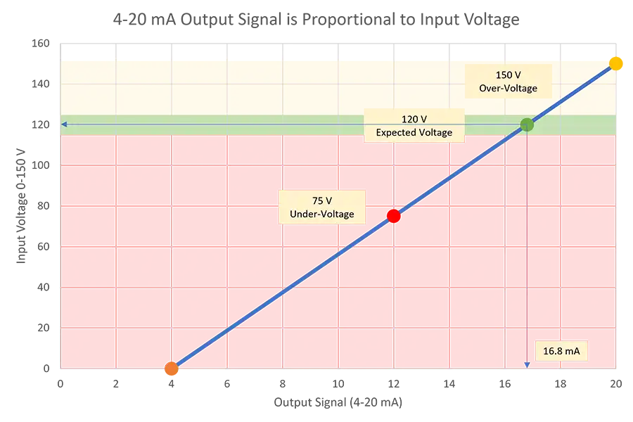
This is a typical example for monitoring 120 VAC line voltage. Choosing a transducer with a range of 0 to 150 VAC allows monitoring of both over-voltage and under-voltage conditions. The table shows corresponding output signals for three types of standard outputs (0-5 VDC, 0-10 VDC, 4-20 mA).

No Power / Under-Voltage:
A voltage transducer with a 4-20 mA output signal is shown in the graph below, using an input range of 0-150 V. When the input voltage is zero volts, the voltage transducer provides 4 mA of current. This is shown by the orange circle. The under-voltage condition remains as the input voltage goes from 0 volts to 120 volts.
Expected Voltage:
The target voltage is 120 V as shown by the green shaded area. When the input voltage is 120 V, the output current will be 16.8 mA as shown by the green dot.
Over-Voltage:
If the input voltage exceeds 120 V and enters the yellow region, then the output signal will be above 16.8 mA until it reaches the maximum input range of 150 V where the output will be 20 mA (yellow dot).

Example 3: Voltage Transducer with bidirectional +/- 300 VDC input range.
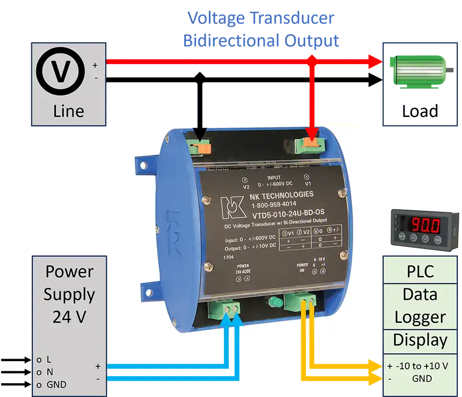
This final example uses a voltage transducer that has an input range that supports bidirectional DC voltage.


In this case, a negative input voltage results in a proportional negative output voltage. A DC motor may reverse direction when
a negative voltage is applied. Thus, the polarity of the output signal will indicate the direction that they motor is turning.
It is important to ensure that the device receiving the output signal can handle the negative voltage range.

What is the difference between a voltage transducer and a current transducer?
Like voltage transducers, current transducers (also called current sensors) are used in manufacturing and industrial applications to monitor processes and control equipment. Current transducers can provide similar benefits as voltage transducers but measure electrical current instead of voltage. They measure an input current and provide a proportional analog output signal.
Often, current transducers are mistakenly called current transformers. Current transformers are designed specifically to step down high currents to a smaller, more manageable current. This is accomplished by using a fixed ratio based on the number of windings around a magnetic core.
Current transducers on the other hand, start with a current transformer, then apply advanced signal conditioning to measure the current source and create a safe proportional output signal. Current transducers require external power to provide the signal conditioning.
So current transducers perform more than a simple step down function as they can measure potentially high current sources and safely convert them to a standard output signal. However, in practice, the two terms get used interchangeably despite having unique characteristics.

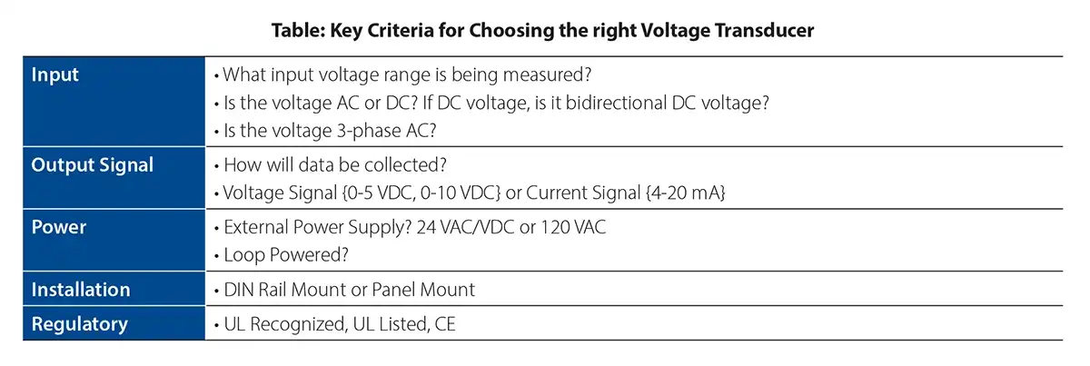
To learn more about choosing the right voltage transducer, see our whitepaper, “How to Choose a Voltage Transducer.”
