As much as we tend to assume that all control systems in the 21st century use programmable logic controllers, DCS or PC based logic, that is overly optimistic. There are countless machines and processes controlled with relays and panel mounted indicators, and while the control industry seems to want all devices to be connected to the Internet of Things (IoT ), getting vintage systems networked will be a challenge. Until this equipment reaches its end of life, there will be a need for much simpler approaches to machine control.
Understanding the current requirements of this equipment is important. Electric motors consume over 60% of the electrical power used worldwide, and they have some specific properties with regard to the amount of current they require. AC “squirrel cage” motors are the most common type used for moving air, liquids and solid materials. When they start, they draw six to ten times the amount of current used when they are operating at full load, but for a relatively short period of time. When the motor output shaft is connected to a load, the motor will draw as much current as is needed to get the load moving. Selection of the motor size should be based on the amount of torque the task will require. If a motor is selected with insufficient horsepower for all possible loads, the motor could overheat or stall soon after installation. If the work requires full horsepower only intermittently it might take much longer to have a failure. Selecting a motor larger than is needed will eliminate those issues, but will use more current than required whenever operating. This makes real time troubleshooting more difficult.
Measuring current is generally an excellent way to detect over or under current conditions. When measuring the current flowing to a motor several issues can be detected and controlled:
- Electric motor driven pumps will draw more current when there is an obstruction in the volute which keeps the impeller from spinning freely; or if a bearing is failing. If the intake or discharge is blocked, the pump will draw less current as the only work being done is spinning the fluid. If the discharge line has become disconnected the loss of head pressure will also cause a drop in current.
- An air handler will show similar symptoms. If the fan blades are not free to move, or the bearings are failing, the drive motor will demand more current. If the blades are not secured to the rotating shaft properly due to a slipping coupling or a broken drive belt, the motor will draw less than normal current.
- A conveyor system will draw more current if the belt is blocked or too heavily loaded with material, and will draw less than normal current if the belts or chains connecting the motor to the conveying belt have broken or fallen off the sprockets or sheaves.
Without a PLC or a panel meter with programmable alarm points, a current operated relay or switch can be set to provide a contact change at a single adjustable current level. Up until now two sensors were required: one to change at high current, the second to change at low current levels. With the new ASP Series, only one sensor is needed.
 ASP Series AC Current Switch
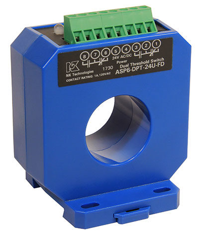
The new ASP Series provides two independently adjustable setpoints. The outputs are two single-pole, double-throw relays. Each relay can switch up to one amp, up to 120 VAC or 30 VDC.
One setpoint opens a contact on high current, while the other opens it on low current. If the application requires the reverse contact action, the ASP can handle that too.
With the ASP, the operator can set an alarm point to trigger a stack light when current reaches a certain point as a caution, and set a second alarm point to shut down the process if the current reaches a more dangerous level. Set up is easy. One sensor, one installation. Snap onto a DIN rail or use screws through mounting holes to a back panel, apply 24 volts for power, and dial in the set points for each relay change.