Many installations use wire larger than the minimum specified by code, often to reduce the voltage loss (drop) 
Since the majority of current sensing methods require a ring surrounding the conductors, most current sensors have been designed to be as small as possible to take up a minimum amount of space in an enclosure. The inside diameter of the sensing ring is nearly the same as the outside diameter of the wire that carries the maximum amount of current for which the sensor is designed. Since the OD of a 4/0 THHN wire rated to carry 200 A is 0.64”, NK Technologies’ designed its solid-core housing (the most common type used) with an aperture of 0.74”. The split-core housing has an aperture of 0.85”. Many competitors borrowed this size criteria for their own products.
If the wire carrying the same 200 A is a little larger, 300MCM THHN, the outside diameter increases to 0.77”. Passing this wire through a solid-core sensor is impossible, but would fit through the split-core models.
There are times where specifications call for two or more wires per phase. Paralleling conductors can make pulling the wire through a conduit and working the wire in the cabinet easier, allowing the cable to be bent so it fits the enclosure using less effort, reducing the chance of damaging the insulation. Two 1 AWG THHN wires carrying 200 A are a minimum of 0.90” wide, so they would not pass through either the standard solid-core or the split-core housing.
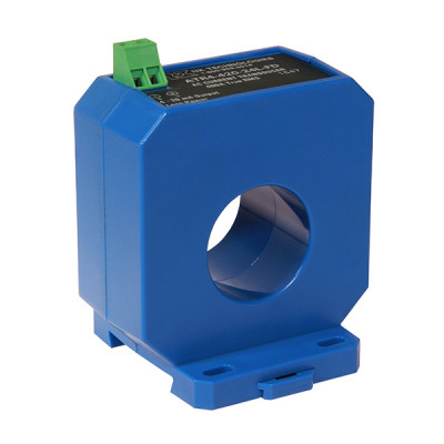
These issues were the driving force behind the design of NK Technologies’ new housing. Not only does the new sensor housing provide an aperture with a 1.31” inside diameter, making feeding the wires through the sensor as effortless as possible, the sensor also fits directly on a DIN rail or can be attached with screws through the base. Overall, the new housing is not much larger than the standard designs.
As with other NK Technologies’ AC current transducers, it is available with a 4–20 mA output signal proportional to the average current (50 or 60 hertz sinusoidal wave shapes) for loads that are powered directly “across the line,” or with the output proportional to the RMS current where the load is controlled by a variable frequency inverter or a phase angle fired heating controller. If the current wave shape is anything other than sinusoidal the RMS version will produce a more accurate measurement signal.
 AT/ATR-FD Series Current Transducer
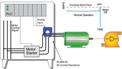
AT/ATR-FD Series Current Transducers provide a current sensor and analog output signal conditioning in a single package. The large, easy to install solid-core design allows for quick installation even in applications where there are multiple conductors per phase. Just thread the conductor through the extra large aperture and reconnect on the other side. The transducer output is powered from excitation voltage of around 24 VDC, using just two wires. The sensor mounts on a back panel or a DIN rail, and is designed to accommodate wire sizes for loads up to 400 A.

