With solar panels becoming more efficient and reliable, the size of the installations are growing at an unimaginable rate. It makes sense to install as many panels in one location as possible, and when open land or rooftop space is available it makes economic sense to energize as many panels possible. The conventional panel fabrication method produces power at 12—13 volts, direct current. With one 50 watt panel producing an actual 39 watts due to losses in efficiency the current is about 3 amps.
By connecting the panel outputs in parallel, the voltage remains low while the current increases: Two panels produce 6 amps, three produce nine, etc. The higher the current, the larger the wire needed to carry the amperage. Transmitting this power a long distance results in a drop in voltage as the distance increases due to the resistance of the conductor composition. When you start at 12 volts, there isn’t a lot to lose.
Another approach is to connect the panels in series effectively increasing the voltage at each connection. With the voltage higher, the current is constant at 3 amps, transmitting an equal amount of power but allowing for smaller conductors at a much lower cost. Connect fifty standard panels in series and the voltage produced will be near 600, which is the rating of the majority of building wire. The current will still be 3 amps if all the connected panels are rated at the same wattage output.
At this point it doesn’t make sense to continue connecting in series due to the insulation levels required beyond 600 volts, but in the past several years we have seen systems producing power up to 1500 volts. With that amount of potential, spacing and insulation is critically important. Arcing across terminations can occur more easily with DC circuits than with AC as AC voltage drops to zero 60 times each second. When the conductors are insulated for the voltage between each or from one to earth ground, the danger is significantly reduced. However, the most efficient way to transport electrical power is via bus bars, which are seldom insulated. Now let’s consider what is required to measure the current or voltage.
Measuring Voltage
The way to measure DC voltage is to make physical contact between two points, either from the positive conductor to the negative conductor, or from either positive or negative to earth. As mentioned, higher voltage requires more spacing between conductors and from the conductor to any metal enclosure or surface. The more space the safer the installation.
Measuring Current
Measuring current is done by surrounding the conductor with a magnetically permeable ring, capturing the magnetic flux developed by the current flowing in the conductor. The nearer to the conductor the better the ring’s ability to measure the magnetic field. This means that any ring must be carefully designed to keep the ring from coming into contact with the conductor and the ring output terminals a fair distance from the energized bar or wire.
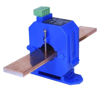
For the easiest installation of a current sensor, one which opens to allow the sensor to surround the conductor without having to slip it over the end of an un-terminated wire or bar is the best option. With the best design, the sensor will be secured onto the conductor so it stays in place. The latest innovation in DC current measurement, the DT-BB Series, does all of this.
 DT-BB Series Current Transducers Measure DC Current up to 1500 Volts
DT-BB Series Current Transducers feature a split-core design that can be installed over existing bus bars or wire and can be mounted on a panel or DIN rail. The DT-BB is rated to measure DC current up to 400 amps and up to 1500 volts. The transducer is available in four ranges from 0–100 to 0–400 amps; three output types: unipolar, bipolar and bidirectional; and three industry standard outputs: 4–20 mA, 0–5 and 0–10 VDC.
The power supply and output signal wires are connected to the sensor with a terminal block which plugs into the header on the top of the sensor. The Innovative design puts the current sensing components in one housing with the signal conditioning, reducing installation time and improving both accuracy and safety.

 DT-BB Series Current Transducers Measure DC Current up to 1500 Volts