Since the early 1980s, NK Technologies has manufactured AC current sensors with ranges
to 200 amps. While  this covers a lot of applications, AC current measurement or control loads over 200 amps require at least two parts (current sensing and signal conditioning), which adds complexity and multiple connections. The use of NK Technologies’ sensors in a one-piece design, proven safe, reliable, and simple to install in applications up to 200 amps, was not an option in applications over 200 amps.
Additionally, our customers asked for larger split-core sensors for many applications, from monitoring building cooling tower fans and irrigation pumps to grinders and shredders in recycling plants. NK Technologies wanted to be sure that our products would suit the largest number of applications and provide the accuracy and reliability our customers expect. This goal has been achieved with the large aperture and split-core sensors.
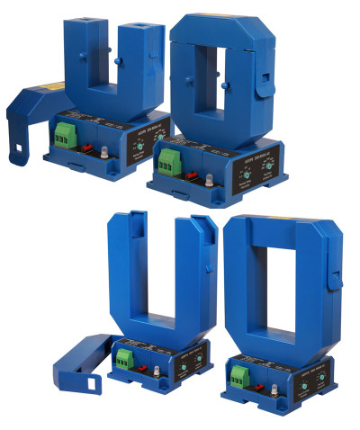
These sensors feature a very innovative modular design. Two sizes of sensing rings are mounted to a common base. Additionally, the rings enclose the core and windings that make up a current transformer. This design approach allows NK Technologies to offer split-core AC current transducers, current relays, and current transformers, all with ranges of 1600 amps.
The smaller of the two rings (MS models for medium split-core) measures 1.19 inches (30.1mm) wide and 2.22 inches (56.4mm) high. This smaller ring is still large enough for two 500MCM THHN or THW wires to be monitored with room to spare. The larger ring measures 2.3 inches (58.4mm) wide and 3.42 inches (86.9mm) high and can accommodate up to six 500MCM THHN or THW wires. National Electric Code section 310 - 10 designates the derating factors for calculating the maximum amount of current allowed in a circuit when using parallel conductors.
The AT series transducers are designed for maximum accuracy when the AC current wave shape is sinusoidal. The ATR series will accurately measure even if the current wave shape is not sinusoidal, whether produced through an inverter or distorted from harmonic currents. The ATR utilizes an RMS algorithm to keep the output signal at the highest level of accuracy possible, even in the most difficult conditions.
The ASXP relay output models provide fully adjustable trip points so that the output relay will change state as the current increases over the trip point to alarm for over-current conditions, or so the relay is actuated during normal conditions and reverts when the current falls below the trip point. There is a two-second delay to keep the output from changing during motor inrush current and a separate adjustable delay to allow a “ride through” of temporary over-current conditions before the relay output changes.
The AT and ATR transducers and the ASXP relays are attached to a base which can be mounted on a DIN rail or attached to a back panel using screws.
The current transformers are designed to hang over the conductors, wire, or bus bar, and MS models include extrusions to allow cable ties to help support the CTs and keep them stationary.
All of the new large aperture models are tested to meet UL standards; the relays and transducers are UL listed. The current transformers are UL recognized as control or monitoring system components.
